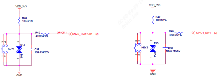
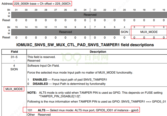
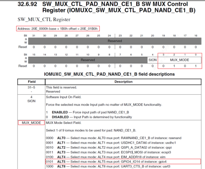
/* set GPIO5_IO03 as GPIO */ staticvolatileunsignedint *IOMUXC_SNVS_SW_MUX_CTL_PAD_SNVS_TAMPER1; /* set GPIO4_IO14 as GPIO */ staticvolatileunsignedint *IOMUXC_SW_MUX_CTL_PAD_NAND_CE1_B;
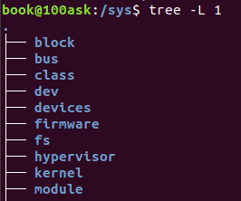
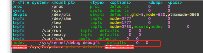
[root@xxx]~# mount /dev/root on / type squashfs (ro,relatime) devtmpfs on /dev type devtmpfs (rw,relatime,size=1381884k,nr_inodes=345471,mode=755) proc on /proc type proc (rw,relatime) #procfs sysfs on /sys type sysfs (rw,relatime) #sysfs nodev on /sys/kernel/debug type debugfs (rw,relatime) #debugfs /dev/mmcblk0p6 on /mnt/cfg type ext4 (rw,sync,relatime) /dev/mmcblk0p7 on /mnt/data type ext4 (rw,sync,relatime) /dev/mmcblk0p7 on /var/log type ext4 (rw,sync,relatime)
fail_printk: printk("unable to get major %d for misc devices\n", MISC_MAJOR); class_destroy(misc_class); fail_remove: remove_proc_entry("misc", NULL); return err; }
num = sscanf(input, "%s %d %d %d", str, &a, &v, &v2); if (num > 4) { dbg_print_usage(link->dev); return -EINVAL; }
dev_info(link->dev, "input = %s %d\n", str, num); /* convert to lower case for following type compare */ p = str; for (; *p; ++p) *p = tolower(*p); n = ARRAY_SIZE(dbg_type); for (i = 0; i < n; i++) { if (!strcmp(str, dbg_type[i])) { t = i; break; } } if (i == n) { dev_info(link->dev, "unknown type(%s)!\n", str); dbg_print_usage(link->dev); return -EINVAL; } switch (t) { case0: /* reset */ if (a > MAX_LINK_NUM) return -EINVAL;
seq_printf(m, "\nModule: [MIPI_RX], Build Time[%s]\n", UTS_VERSION); seq_puts(m, "\n------------Combo DEV ATTR--------------\n"); for (i = 0; i < MAX_LINK_NUM; i++) if (dev->link[i].is_on) cif_show_dev_attr(m, &dev->link[i].attr);
ELF Header: Magic: 7f 45 4c 46 01 01 01 00 00 00 00 00 00 00 00 00 Class: ELF32 Data: 2's complement, little endian Version: 1 (current) OS/ABI: UNIX - System V ABI Version: 0 Type: REL (Relocatable file) Machine: ARM Version: 0x1 Entry point address: 0x0 Start of program headers: 0 (bytes into file) Start of section headers: 264 (bytes into file) Flags: 0x5000000, Version5 EABI Size of this header: 52 (bytes) Size of program headers: 0 (bytes) Number of program headers: 0 Size of section headers: 40 (bytes) Number of section headers: 10 Section header string table index: 7
ELF Header: Magic: 7f 45 4c 46 01 01 01 00 00 00 00 00 00 00 00 00 Class: ELF32 Data: 2's complement, little endian Version: 1 (current) OS/ABI: UNIX - System V ABI Version: 0 Type: EXEC (Executable file) Machine: ARM Version: 0x1 Entry point address: 0x82e1 Start of program headers: 52 (bytes into file) Start of section headers: 4508 (bytes into file) Flags: 0x5000402, has entry point, Version5 EABI, hard-float ABI Size of this header: 52 (bytes) Size of program headers: 32 (bytes) Number of program headers: 9 Size of section headers: 40 (bytes) Number of section headers: 30 Section header string table index: 27
和2.2.1 可重定位目标文件对比,有以下几点不同:
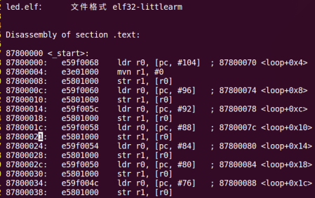
Type 由 REL (Relocatable file) 变成了 EXEC (Executable file),表示这是一个可执行文件.
Entry point address,即程序入口为 0x82e1 而不再是 0,表示程序在加载时需要将入口代码放到该地址执行.
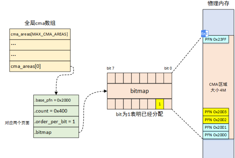
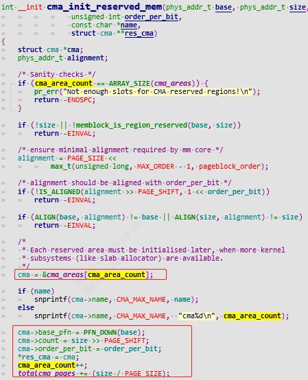
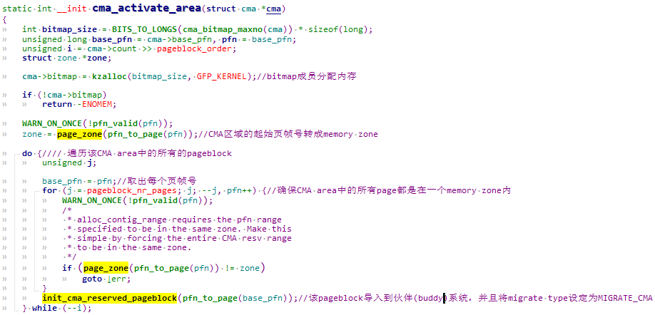
/** * cma_release() - release allocated pages * @cma: Contiguous memory region for which the allocation is performed. * @pages: Allocated pages. * @count: Number of allocated pages. * * This function releases memory allocated by cma_alloc(). * It returns false when provided pages do not belong to contiguous area and * true otherwise. */ boolcma_release(struct cma *cma, conststruct page *pages, unsignedint count);
对于自旋锁而言,如果自旋锁 正在被线程 A 持有,线程 B 想要获取自旋锁,那么线程 B 就会处于忙循环-旋转-等待状态,线 程 B 不会进入休眠状态或者说去做其他的处理,而是会一直傻傻的在那里“转圈圈”的等待锁 可用。比如现在有个公用电话亭,一次肯定只能进去一个人打电话,现在电话亭里面有人正在 打电话,相当于获得了自旋锁。此时你到了电话亭门口,因为里面有人,所以你不能进去打电 话,相当于没有获取自旋锁,这个时候你肯定是站在原地等待,你可能因为无聊的等待而转圈 圈消遣时光,反正就是哪里也不能去,要一直等到里面的人打完电话出来。终于,里面的人打 完电话出来了,相当于释放了自旋锁,这个时候你就可以使用电话亭打电话了,相当于获取到 了自旋锁。
自旋锁的“自旋”也就是“原地打转”的意思,“原地打转”的目的是为了等待自旋锁可以 用,可以访问共享资源。把自旋锁比作一个变量 a,变量 a=1 的时候表示共享资源可用,当 a=0 的时候表示共享资源不可用。现在线程 A 要访问共享资源,发现 a=0(自旋锁被其他线程持有), 那么线程 A 就会不断的查询 a 的值,直到 a=1。可
void spin_lock_irqsave(spinlock_t *lock,unsigned long flags)
保存中断状态,禁止本地中断,并获取自旋锁。
void spin_unlock_irqrestore(spinlock_t*lock, unsigned long flags)
将中断状态恢复到以前的状态,并且激活本地中断,释放自旋锁
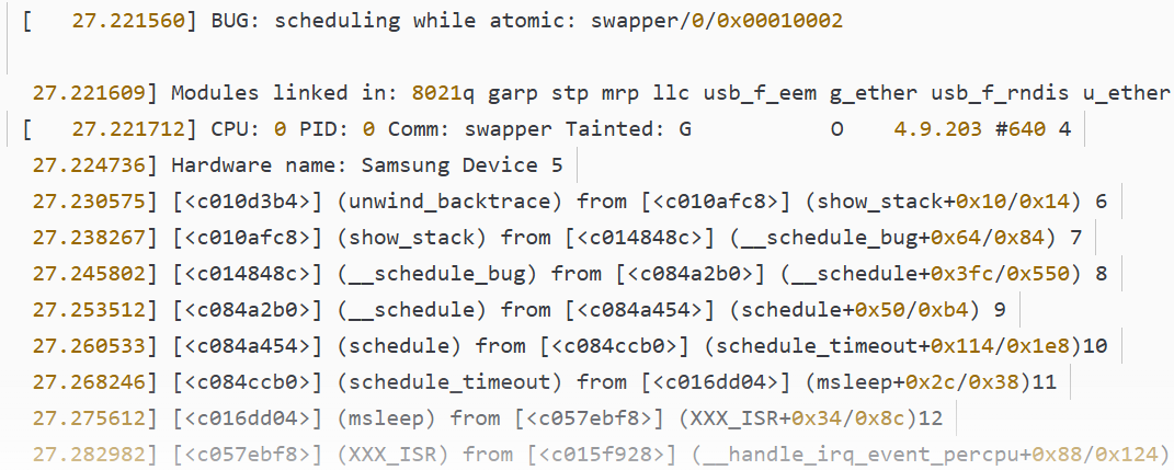
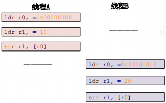
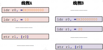
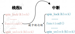
如下图就是没有禁止本地中断导致死锁的例子:
线程 A 先运行,并且获取到了 lock 这个锁,当线程 A 运行 functionA 函 数的时候中断发生了,中断抢走了 CPU 使用权。右边的中断服务函数也要获取 lock 这个锁, 但是这个锁被线程 A 占有着,中断就会一直自旋,等待锁有效。但是在中断服务函数执行完之前,线程 A 是不可能执行的,线程 A 说“你先放手”,中断说“你先放手”,场面就这么僵持着, 死锁发生!
相比于自旋锁,信号量可以使线程进入休眠状态,比如 A 与 B、C 合租了一套房子,这个 房子只有一个厕所,一次只能一个人使用。某一天早上 A 去上厕所了,过了一会 B 也想用厕 所,因为 A 在厕所里面,所以 B 只能等到 A 用来了才能进去。B 要么就一直在厕所门口等着, 等 A 出来,这个时候就相当于自旋锁。B 也可以告诉 A,让 A 出来以后通知他一下,然后 B 继 续回房间睡觉,这个时候相当于信号量。可以看出,使用信号量会提高处理器的使用效率,毕 竟不用一直傻乎乎的在那里“自旋”等待。但是,信号量的开销要比自旋锁大,因为信号量使 线程进入休眠状态以后会切换线程,切换线程就会有开销。
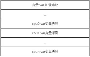
在 SMP 架构中,每个 CPU 都拥有自己的高速缓存,通常,L1 cache 是 CPU 独占的,每个 CPU 都有一份,它的速度自然是最快的,而 L2 cache 通常是所有 CPU 共享的高速缓存,当 CPU 载入一个全局数据时,会逐级地查看高速缓存,如果没有在缓存中命中,就从内存中载入,并加入到各级 cache 中,当下次需要读取这个值时,直接读取 cache 。
// 获取当前CPU的percpu变量的值 int value = per_cpu(val, smp_processor_id()); // 遍历所有CPU,并打印percpu变量的值 for_each_possible_cpu(cpu) { value = per_cpu(val, cpu); printk(KERN_INFO "my_percpu_var on CPU%d is %d\n", cpu, value); }
/*put_cpu_var 和 get_cpu_var 是成对出现的,因为这段期间内静止内核抢占, *它们之间的代码不宜执行太长时间。 */ int *pint = &get_cpu_var(val);//获取当前 CPU 的 percpu 变量的地址进行操作 *pint++; put_cpu_var(val);
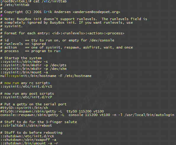
<id>:<runlevels>:<action>:<process> <id>:每个指令的标识符,不能重复。但是对于 busybox 的 init 来说,<id>有着特殊意义。对于 busybox 而言<id>用来指定启动进程的控制 tty,一般我们将串口或者 LCD 屏幕设置为控制 tty。 <runlevels>:对 busybox 来说此项完全没用,所以空着。 <action>:动作,用于指定<process>可能用到的动作: busybox 支持的动作如下: sysinit: 在系统初始化的时候 process 才会执行一次。 respawn: 当 process 终止以后马上启动一个新的。 askfirst:和 respawn 类似,在运行 process 之前在控制台上显示“Please press Enter to activate this console.”。只要用户按下“Enter”键以后才会执行 process。 wait: 告诉 init,要等待相应的进程执行完以后才能继续执行。 once: 仅执行一次,而且不会等待 process 执行完成。 restart: 当 init 重启的时候才会执行 procee。 ctrlaltdel: 当按下 ctrl+alt+del 组合键才会执行 process。 shutdown: 关机的时候执行 process。 <process>:具体的动作,比如程序、脚本或命令等
我们的/etc/inittab内容设置如下:
1 2 3 4 5 6 7
#etc/inittab ::sysinit:/etc/init.d/rcS console::askfirst:-/bin/sh ::restart:/sbin/init ::ctrlaltdel:/sbin/reboot ::shutdown:/bin/umount -a -r ::shutdown:/sbin/swapoff -a
# Generated by NetworkManager nameserver 192.168.248.2
一般将nameserver设置成网关地址,再加入8.8.8.8和114.114.114.114
ping blog.csdn.com:
1 2 3 4
[root@node2 ~]# ping blog.csdn.com PING blog.csdn.com.com (45.11.57.36) 56(84) bytes of data. 64 bytes from comcomproxy1.com.com (45.11.57.36): icmp_seq=1 ttl=44 time=291 ms 64 bytes from comcomproxy1.com.com (45.11.57.36): icmp_seq=2 ttl=44 time=270 ms
ping blog,发现不通,需要设置domain域:
1 2
[root@node2 ~]# ping blog ping: blog: 未知的名称或服务
调整/etc/resolv.conf配置文件,添加domain
1 2 3 4
[root@node2 ~]# vi /etc/resolv.conf # Generated by NetworkManager nameserver 192.168.248.2 domain csdn.net
再次ping blog, ping不完整域名会自动补全
1 2 3
[root@node2 ~]# ping blog PING blog.csdn.net (182.92.187.217) 56(84) bytes of data. 64 bytes from 182.92.187.217 (182.92.187.217): icmp_seq=1 ttl=89 time=20.4 ms
调整/etc/resolv.conf配置文件,添加search
1
2
3
4
[root@node2 ~]# vi /etc/resolv.conf # Generated by NetworkManager nameserver 192.168.248.2 search abc.com csdn.net