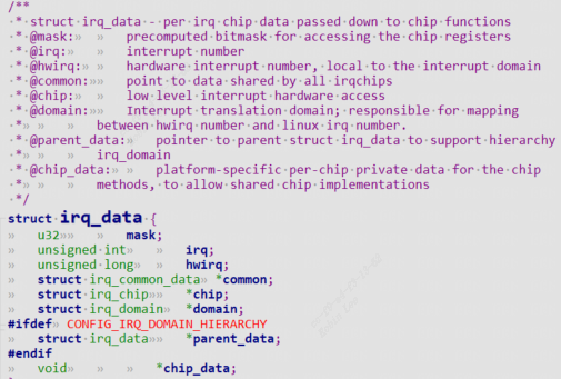
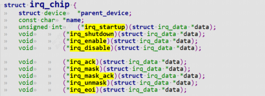
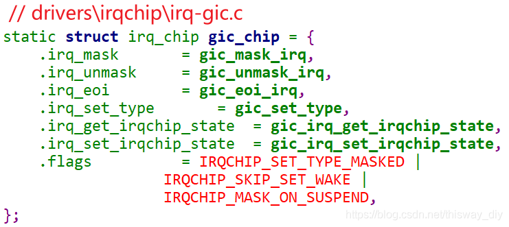
* @irq_startup: start up the interrupt (defaults to ->enable ifNULL) * @irq_shutdown: shut down the interrupt (defaults to ->disable ifNULL) * @irq_enable: enable the interrupt (defaults to chip->unmask ifNULL) * @irq_disable: disable the interrupt * @irq_ack: start of a new interrupt * @irq_mask: mask an interrupt source * @irq_mask_ack: ack and mask an interrupt source * @irq_unmask: unmask an interrupt source * @irq_eoi: end of interrupt
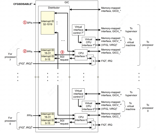
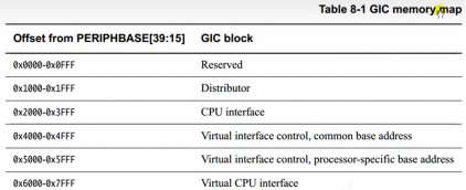
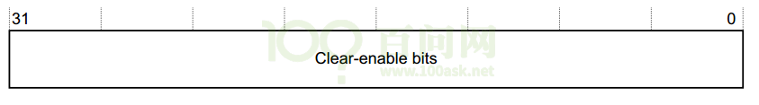
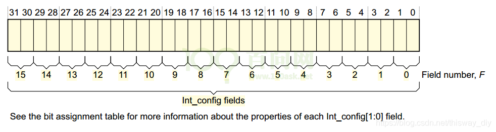
对于interrtups ID m,如下计算:
n = m DIV 32,GICD_ISENABLERn里的n就确定了;
GICD_ISENABLERn在GIC内部的偏移地址是多少?0x100+(4*n)
使用GICD_ISENABLERn中哪一位来表示interrtups ID m?
bit = m mod 32。
对于interrtups ID m,如下计算:
n = m DIV 32,GICD_ISENABLERn里的n就确定了;
GICD_ISENABLERn在GIC内部的偏移地址是多少?0x100+(4*n)
使用GICD_ISENABLERn中哪一位来表示interrtups ID m?
bit = m mod 32。
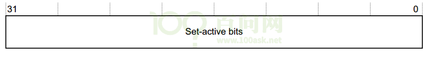
对于interrtups ID m,如下计算:
n = m DIV 32,GICD_ISACTIVERn里的n就确定了;
GICD_ISACTIVERn在GIC内部的偏移地址是多少?0x300+(4*n)
使用GICD_ISACTIVERn 中哪一位来表示interrtups ID m?
bit = m mod 32。
对于interrtups ID m,如下计算:
n = m DIV 32,GICD_ICACTIVERn里的n就确定了;
GICD_ICACTIVERn 在GIC内部的偏移地址是多少?0x380+(4*n)
使用GICD_ICACTIVERn中哪一位来表示interrtups ID m?
bit = m mod 32。
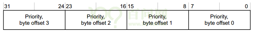
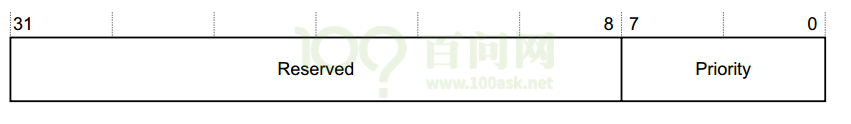
对于interrtups ID m,如下计算:
n = m DIV 4,GICD_IPRIORITYRn里的n就确定了;
GICD_IPRIORITYRn在GIC内部的偏移地址是多少?0x400+(4*n)
使用GICD_IPRIORITYRn中4个字节中的哪一个来表示interrtups ID m的优先级?
byte offset = m mod 4。
byte offset 0对应寄存器里的[7:0];
byte offset 1对应寄存器里的[15:8];
byte offset 2对应寄存器里的[23:16];
byte offset 3对应寄存器里的[31:24]。
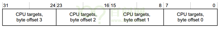
对于interrtups ID m,如下计算:
n = m DIV 4,GICD_ITARGETSRn里的n就确定了;
GICD_ITARGETSRn在GIC内部的偏移地址是多少?0x800+(4*n)
使用GICD_ITARGETSRn中4个字节中的哪一个来表示interrtups ID m的目标CPU?
byte offset = m mod 4。
byte offset 0对应寄存器里的[7:0];
byte offset 1对应寄存器里的[15:8];
byte offset 2对应寄存器里的[23:16];
byte offset 3对应寄存器里的[31:24]。
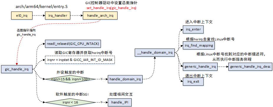
if (likely(irqnr > 15 && irqnr < 1020) || irqnr >= 8192) { ------(2) int err;
if (static_key_true(&supports_deactivate)) gic_write_eoir(irqnr); else isb();
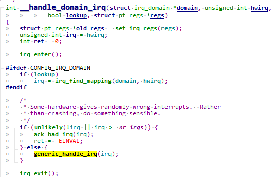
err = handle_domain_irq(gic_data.domain, irqnr, regs); ------(3) if (err) { WARN_ONCE(true, "Unexpected interrupt received!\n"); if (static_key_true(&supports_deactivate)) { if (irqnr < 8192) gic_write_dir(irqnr); } else { gic_write_eoir(irqnr); } } continue; } if (irqnr < 16) { ------(4) gic_write_eoir(irqnr); if (static_key_true(&supports_deactivate)) gic_write_dir(irqnr); #ifdef CONFIG_SMP /* * Unlike GICv2, we don't need an smp_rmb() here. * The control dependency from gic_read_iar to * the ISB in gic_write_eoir is enough to ensure * that any shared data read by handle_IPI will * be read after the ACK. */ handle_IPI(irqnr, regs); ------(5) #else WARN_ONCE(true, "Unexpected SGI received!\n"); #endif continue; } } while (irqnr != ICC_IAR1_EL1_SPURIOUS); }
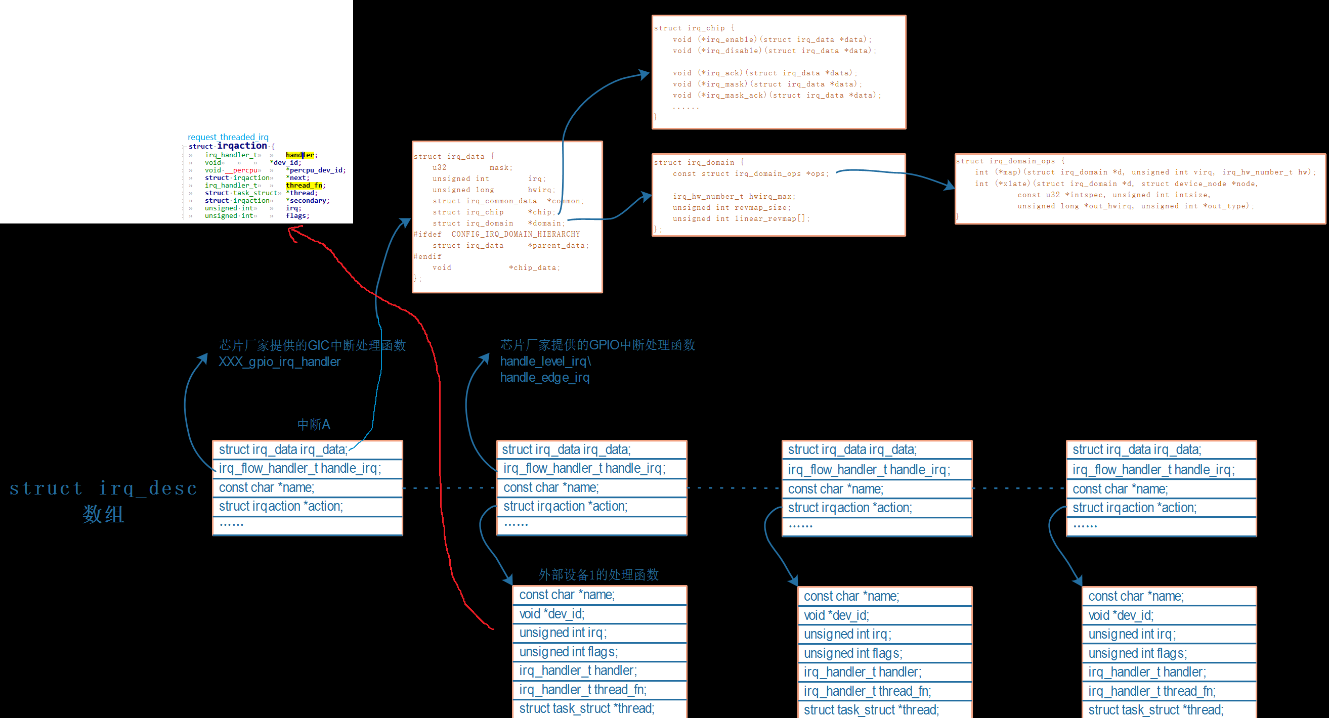
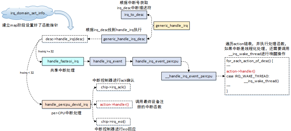
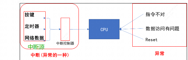
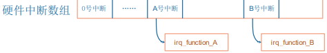
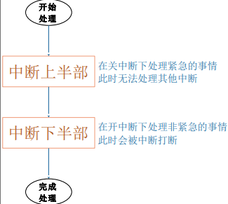
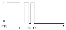
中断 A 正在处理的过程中,假设又发生了中断 B,那么在栈里要保存 A 的现场,然后处理 B。在处理 B 的过程中又发生了中断 C,那么在栈里要保存 B 的现场,然后处理C。 如果中断嵌套突然暴发,那么栈将越来越大,栈终将耗尽。 为了防止这种情况发生,也是为了简单化中断的处理,在 Linux 系统上规定中断无法嵌套:即当前中断 A 没处理完之前,不会响应另一个中断 B(即使它的优先级更高)。
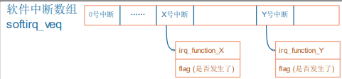
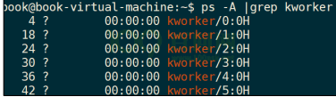
以前用 work 来线程化地处理中断,一个 worker 线程只能由一个 CPU 执行,多个中断的 work 都由同一个 worker 线程来处理,在单 CPU 系统中也只能忍着了。但是在 SMP 系统中,明明有那么多 CPU 空着,你偏偏让多个中断挤在这个CPU 上? 新技术 threaded irq,为每一个中断都创建一个内核线程;多个中断的内核线程可以分配到多个 CPU 上执行,这提高了效率。
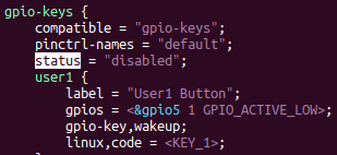
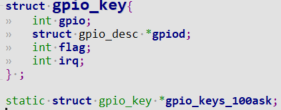
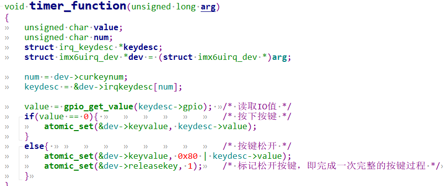
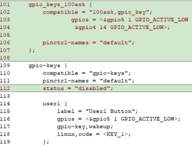
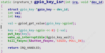
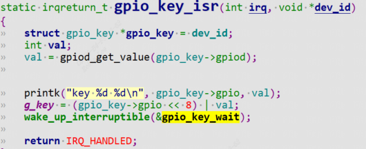
structgpio_key{ int gpio; structgpio_desc *gpiod; int flag; int irq; } ; staticstructgpio_key *gpio_keys_100ask; staticint major = 0; staticstructclass *gpio_key_class;
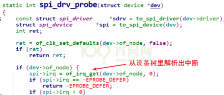
staticinlinestruct device_node *of_parse_phandle(conststruct device_node *np, constchar *phandle_name, int index); //例如: // get reserved memory-region res_node = of_parse_phandle(np, "memory-region", 0); if (!res_node) { dev_err(&pdev->dev, "failed to get memory region node\n"); return -ENODEV; } ret = of_address_to_resource(res_node, 0, res); if (ret) { dev_err(&pdev->dev, "failed to get reserved region address\n"); return -ENODEV; }
/* * Find a property with a given name for a given node * and return the value. */ constvoid *of_get_property(conststruct device_node *np, constchar *name, int *lenp); //eg: of_find_property(dtsled.nd, "compatible", NULL);
* of_property_count_elems_of_size - Count the number of elements in a property * * @np: * device node from which the property value is to be read. * @propname: name of the property to be searched. * @elem_size: size of the individual element * * Search for a property in a device node and count the number of elements of * size elem_size in it. Returns number of elements on sucess, -EINVAL if the * property does not exist or its length does not match a multiple of elem_size * and -ENODATA if the property does not have a value. */ intof_property_count_elems_of_size(conststruct device_node *np, constchar *propname, int elem_size)
在内核中,使用同一个芯片的板子,它们所用的外设资源不一样,比如 A 板用 GPIO A,B 板用 GPIO B, 如果用plateform_device定义资源信息,那么每次单板硬件资源变动后,都要改驱动程序源码,重新编译驱动,重新加载驱动,非常麻烦。 随着 ARM 芯片的流行,内核中针对这些 ARM 板保存有大量的、没有技术含量的文件。 Linus 大发雷霆:"this whole ARM thing is a f*cking pain in the ass"。于是,Linux 内核开始引入设备树。 设备树并不是重新发明出来的,在 Linux 内核中其他平台如 PowerPC,早就使用设备树来描述硬件了。 设备树只是用来给内核里的驱动程序,指定硬件的信息。
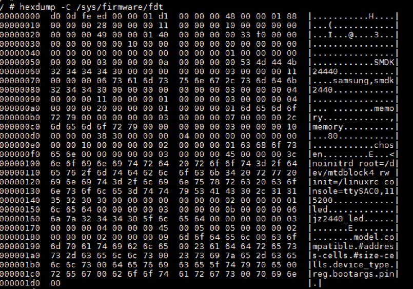
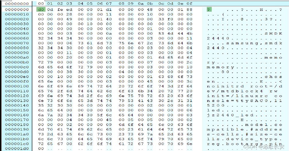
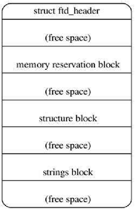
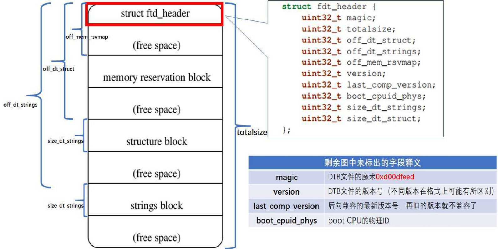
structfdt_header { fdt32_t magic; /* magic word FDT_MAGIC */ fdt32_t totalsize; /* total size of DT block */ fdt32_t off_dt_struct; /* offset to structure */ fdt32_t off_dt_strings; /* offset to strings */ fdt32_t off_mem_rsvmap; /* offset to memory reserve map */ fdt32_t version; /* format version */ fdt32_t last_comp_version; /* last compatible version */ /* version 2 fields below */ fdt32_t boot_cpuid_phys; /* Which physical CPU id we're booting on */ /* version 3 fields below */ fdt32_t size_dt_strings; /* size of the strings block */ /* version 17 fields below */ fdt32_t size_dt_struct; /* size of the structure block */ };
totalsize: 这个设备树的size,也可以理解为所占用的实际内存空间。 off_dt_struct: offset to dt_struct,表示整个dtb中structure部分所在内存相对头部的偏移地址 off_dt_strings: offset to dt_string,表示整个dtb中string部分所在内存相对头部的偏移地址 off_mem_rsvmap: offset to memory reserve map,dtb中memory reserve map所在内存相对头部的偏移地址